G-1090 Installation Guidelines
Choosing the optimal location
The INVOLI support team is available to help identify the most suitable locations for receiver placement. This is especially crucial when the receivers are intended to operate in a cluster for multilateration purposes. If a receiver is already in use, its reception capabilities can be assessed to determine whether the current installation is adequate or if adjustments are necessary.
Pole mounting
Use the following guidelines to mount the G-1090 Air traffic receiver onto a pole:
1. Fasten the cross bracket on the bottom of the enclosure with four M6x12 bolts.

2. Wrap the two clamp halves around the pole and tighten them using the included M6x110 bolts, washers, and nuts (Note that the maximum pole diameter for this mounting is 11 cm).

3. Attach the pole clamp to the cross bracket by using the last part of the mounting kit, securing it with M6x30 bolts, washers, and nuts.

The G-1090 can be attached to a horizontal pole without using the 90° angle converter piece if required.
Antenna mounting
The illustration below presents the top part of the G-1090 air traffic receiver, indicating the antenna ports. For insights on the Flarm or UAT options, please check the subsequent article, which showcases pictures of the installed Flarm and UAT antennas.
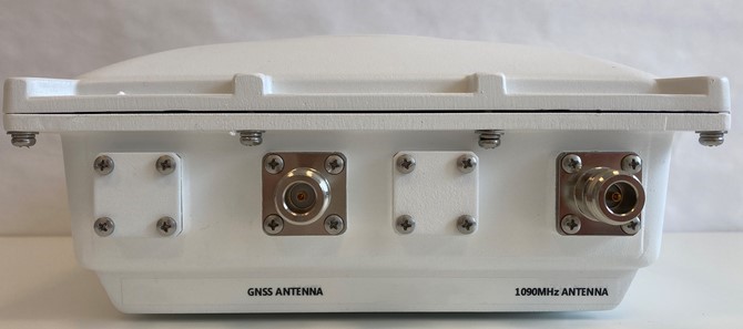
Fasten the GPS antenna and the 1090 MHz antenna to their N connectors. For the 1090 MHz antenna, a male-to-male N-type adapter should be used. The picture below shows the antennas installed correctly:
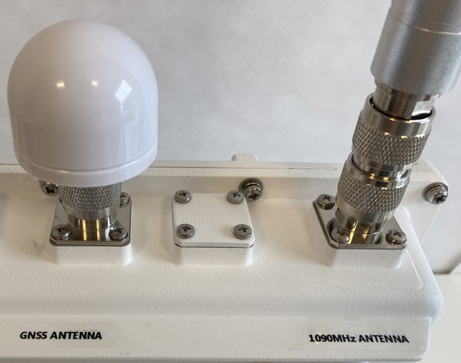
ATTENTION! To avoid oxidation of connectors and prevent water from entering, it is highly advisable to wrap all antenna connectors, including the GPS antenna, with insulation tape. Please use special tape, like TESA extra Power Extreme Repair tape. |
Ethernet cable connection
For installations in outdoor environments, the Ethernet cable that powers the receiver and provides internet connectivity must be connected with the included IP67 connector for the RJ45 cable.
ATTENTION! Not adhering to this guideline may void the warranty for the receiver. |
Installation notes
It is highly recommended that several pictures of the installation from different viewpoints be taken. These photos can help identify problems later if the installation does not operate as expected.